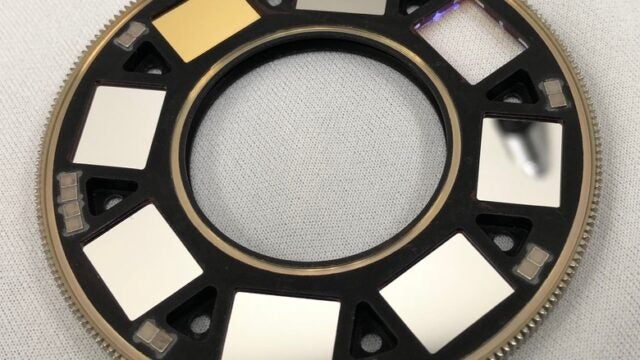
2021-02-14
The Mastcam-Z Filter Set: How Perseverance Will See the Colors of Mars
By Emily Lakdawalla and Melissa Rice
When the Perseverance rover lands on February 18, it will bring 25 cameras to Mars, more “eyes” than any previous spacecraft. Four of those will fly away and crash with the landing hardware, two will land and fly again aboard the Ingenuity helicopter, and the rest will explore Mars from the rover body and mast. Most of those cameras will see in color, but the Mastcam-Z cameras – which have been tuned to the specific colors of Mars – will see the landscape more like a Martian would.
Human eyes evolved under Earth’s sky and solar illumination to detect subtle differences in blues, greens, reds, and all hues in between (which, for example, allows us to spot a piece of ripe fruit amidst dense vegetation under a bright blue sky). Earth color sensitivity isn’t very useful on Mars, where everything appears to be some shade of orange-brown. But the Mastcam-Z cameras can pick out subtle differences in oranges, reds, and near-infrared. These are the wavelengths in which Mars becomes vibrant. With Mastcam-Z, scientists can spot the rocks that are “ripe for the picking” at Jezero crater.
Mastcam-Z’s color selections follow directly from those of Mastcam on Curiosity, Pancam on Spirit and Opportunity, and the Imager for Mars Pathfinder. There are key differences, though, between Mastcam-Z and its predecessors that will improve how it sees Mars.
Multispectral Imaging on Mastcam and Mastcam-Z
Just as with Mastcam, Mastcam-Z will most often produce ordinary human-vision-like color (red, green and blue, or “RGB”) images of Mars much like consumer digital cameras do. For additional science, the two Mastcam-Z cameras will each have a filter wheel behind the optics, similar to what the Mastcam cameras used:
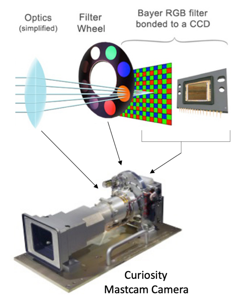
How a Mastcam camera sees color Light enters the camera’s optics and passes through one of 8 filters in the filter wheel before hitting the red, green and blue Bayer filters that are bonded to the CCD detector. This is a schematic cartoon only; components are not shown to scale. NASA / JPL / ASU / Jim Bell / H. Kline
Filters only allow light of certain wavelengths to pass through. In an ideal world, if your cameras had tons of filters that were able to map out how a single spot reflects light at many wavelengths across the spectrum, you could determine the presence of specific minerals based on how their brightness varies with wavelength. Unfortunately, the real world is not so straightforward. Rocks have mixtures of minerals. Minerals have mixtures of compositions. Different minerals have overlapping spectral features that can be hard to pull apart. Some minerals exhibit dips in brightness (absorptions) at specific wavelengths where others might reveal reflectance peaks. Absolutely everything on Mars is covered with at least some dust. Filter wheels can’t hold enough filters to map out every little spectral feature that a spectroscopist would like to study.
Still, taking images taken through just a handful of filters (a method called “multispectral imaging”) can be useful. Multispectral images can help scientists survey a broad landscape for compositional variety, showing which rocks look similar to and different from others. Scientists will classify the observed rocks and soils into spectral groups, and look for good rover parking spots within the arm’s reach of several different rock types. Then, when the rover examines the rocks with its complete set of science instruments, the science team gains a much more detailed and robust understanding of each rock’s mineralogy and can extrapolate those analyses and interpretations to a broader area.
That’s how multispectral imaging has worked on Curiosity, and things will be similar for Perseverance. But in designing Mastcam-Z, the team had the opportunity to ask: Should we send the same filters to Mars with Mastcam-Z that we had on Mastcam, or different ones? If different, what wavelengths will give us better vision of the mineralogical diversity in the rover’s neighborhood?
Color Imaging 101
Before we can talk about filter choices, we have to explain something about how color imaging works on both Mastcam and Mastcam-Z. Usually, spacecraft cameras have detectors made of big arrays of pixels that all detect light the same way. To take color pictures, most spacecraft cameras shoot three separate pictures through red, green, and blue filters. But on a Mastcam detector, every individual pixel is permanently covered with a teeny tiny red, green, or blue filter. The filtered pixels are laid out in a pattern of 2-by-2 arrays that each contain one red, two green, and one blue pixel. This is called a “Bayer pattern filter,” named after its inventor, imaging scientist Bryce E. Bayer. Here’s a diagram of that:
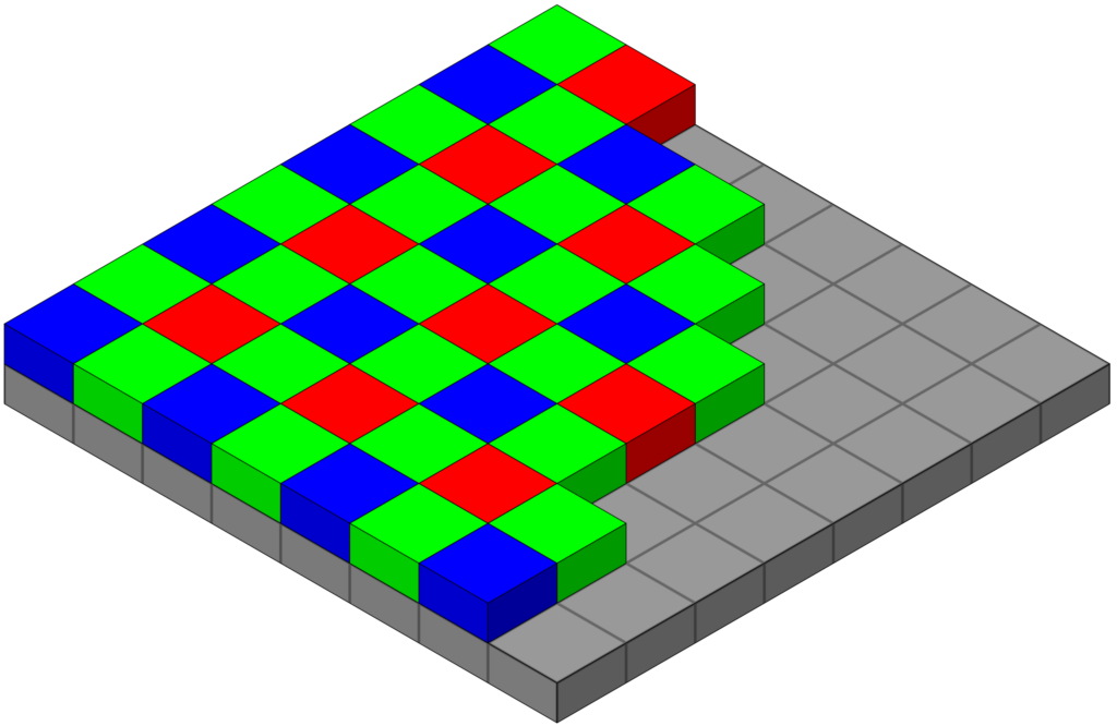
Bayer pattern The arrangement of red, green and blue color filters on the pixel array of a CCD detector. (Wikipedia)
Mastcam gets color photos with only a single exposure; the color information from that checkerboard of differently-filtered pixels is interpolated to fill in all the gaps. That’s how standard digital cameras – like the one in your smartphone – take color images as well.
Here is what a Mastcam photo looks like without interpolation among the different pixels. Can you see the checkerboard, and how it maps to the pattern of colored pixels?
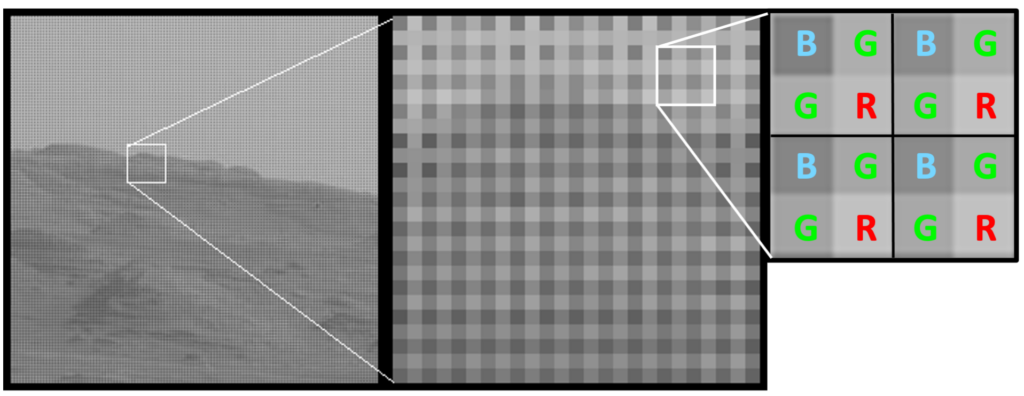
Example Mastcam image without Bayer interpolation Zooming into the original image, you can see the checkerboard pattern due to the different amounts of light transmitted through the red, green, and blue Bayer pixels. MSSS / Emily Lakdawalla / Melissa Rice
The reason for the checkerboard pattern is the fact that, overall, Mars’ rocks and sky are reddish, meaning that they reflect more light in longer than shorter wavelengths. For the most part, the brightest pixels in the checkerboard are from pixels covered with red filters, and the darkest are from pixels covered with blue filters. To turn this image into a color picture, it must be “de-mosaicked.” To do this, you take only the green pixels, and interpolate values into the places where the red and blue pixels were; you take the blue pixels, and interpolate values into the red and green areas; and same for red. There are lots of different, often computationally intense ways of de-mosaicking Bayer-filtered images to turn them into color. The result looks quite smooth, as you can see below.
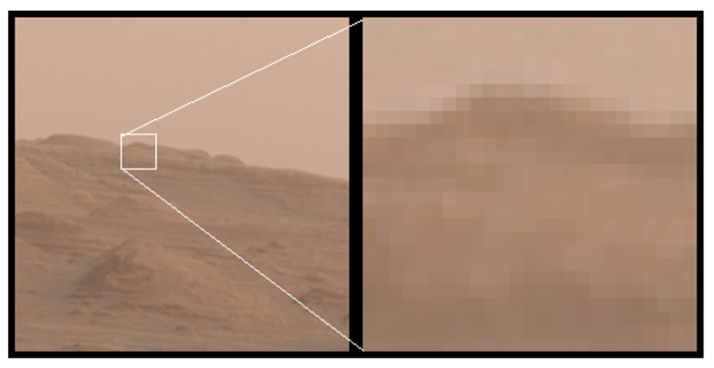
Example of a de-mosaicked Mastcam image Zooming into an interpolated image, you can see that each pixel contains RGB color information, but with a loss of resolution compared to the original image. MSSS / Emily Lakdawalla
This method saves a lot on data volume and file management; it’s a color image made with only as much data as is usually involved in a single black-and-white image. The downside is that there’s a lot of interpolation involved, and there isn’t actually as much detail in the image as its resolution would suggest.
Seeing Beyond RGB with the Filter Set
If Mastcam and Mastcam-Z could see only in those red, green, and blue wavelengths colored by the Bayer filters, there would limited value in doing multispectral imaging. But underneath those Bayer filters, the detector is capable of detecting light at much longer wavelengths, out to 1100 nanometers. Cleverly, the red, green, and blue Bayer filters are designed to be “leaky” in long wavelengths – they all let some light through beyond a wavelength of around 790 nanometers. Beyond 840 nanometers, they are all equally transparent. So if you use filters that let infrared wavelengths of light through to the detectors, you can use the Mastcam-Z cameras like traditional scientific cameras, pretty much ignoring the Bayer filters, and exploring the local mineralogy with a selected set of expanded wavelengths.
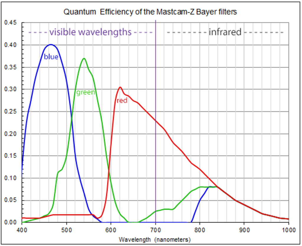
Mastcam-Z Bayer filter profiles Quantum efficiency curves for the Mastcam Bayer filters (L0 and R0 RGB), showing where the bands are “leaky” to near-infrared light beyond 800 nanometers. Emily Lakdawalla / MSSS
Each Mastcam-Z camera has an 8-position filter wheel, so there are 16 total spots available for different filters. In the initial instrument proposal to NASA, the Mastcam-Z team had suggested a filter set identical to Curiosity Mastcam as a starting point, but knew they wanted to make some changes in order to better detect mineralogical differences. At their first meeting after the rover’s instrument selections in 2014, the Mastcam-Z team formed a Multispectral Working Group of scientists who would explore these options. The Working Group met – and still meets – regularly to plan for using the filter set on Mars, and is led by Melissa Rice and Jeff Johnson. Emily Lakdawalla was a member of the Mastcam-Z team and the Multispectral Working Group until her departure from The Planetary Society.
There were lots of decisions to be made about what each of these 16 filters would do, and how they would be arranged between the two cameras. One thing that would definitely not change from Mastcam, however, would be the “clear” filter in each eye that allows for ordinary RGB imaging. “Clear” is in quotes because, unlike in most spacecraft cameras, it’s not just a blank window. Because of the infrared leakiness of the red, green, and blue Bayer filters, the “clear” filter must block out infrared wavelengths, only permitting visible light (with wavelengths of 400 to 700 nanometers) to pass to the detector. And like Mastcam, each “clear” filter would be in filter wheel position zero (called “L0” and “R0” for the left and right cameras), which is the “home” position of the filter wheels. That’s so if anything ever happens to a filter wheel motor, and we end up stuck looking through a single filter for the rest of the mission, we can still take RGB images.
The Multispectral Working Group then had 7 more filters in each eye to work with, and some questions: How can Mastcam-Z best take pictures of the Sun to study the dusty atmosphere? Are there specific colors that should be added to Curiosity Mastcam’s initial set of colors for Mastcam-Z? How much overlap should there be between filters in the two cameras? How should the different filters be arranged between the two Mastcam-Z eyes?
Neutral Density Filters for Looking at the Sun
Each filter wheel on Curiosity’s Mastcams carries one neutral-density filter, which reduces light entering the camera across all wavelengths, like a piece of welder’s glass. These are for imaging the Sun, which the rover does in order to study dust in the sky (“atmospheric opacity”). Observing the Sun also allows the rover to watch transits of the Sun by Phobos and Deimos, which provides useful science data on the orbits of the two fast-moving moons.

Transit of Deimos, Curiosity sol 42 (aligned) 95 images of the Sun taken by Curiosity on sol 42 were aligned to make this animation of Deimos transiting the Sun. NASA / JPL / MSSS / Emily Lakdawalla
Curiosity Mastcam’s left eye has a very dark neutral-density (ND) filter in a near-infrared wavelength (880 nanometers) at which all the Bayer filters are equally transparent. Mastcam’s right eye has a blue-colored neutral-density filter, so gets signal only on one of every four pixels (the blue pixels in the Bayer pattern). For Mastcam-Z, atmospheric science expert Mark Lemmon proposed flying a copy of Mastcam’s 880-nanometer filter, but not re-flying the blue-colored one. Instead, he proposed a broadband clear filter with a stronger neutral density shading than Mastcam’s (ND6 instead of ND5, or ten times less transmissive). That way, atmospheric opacities can be derived in all three Bayer filter wavelengths: “three for the price of one.”
Mastcam-Z’s solar filters were put in the last filter wheel position, as they had been with Curiosity Mastcam and Spirit and Opportunity Pancam previously: L7 and R7.
Duplicating Filters for Stereo Imaging
Because stereo imaging is also important for Mastcam-Z, the team wanted to have at least one pair of identical filters in each eye (in addition to the identical RGB that can be done through the “clear” L0 and R0 filters). Curiosity Mastcam had three sets of so-called “narrowband” stereo filters: two at the shortest wavelength end (L2/R2 at 445 nanometers; and L1/R1 at 527 nanometers) and another at the longest wavelength end (L6/R6 at 1013 nanometers).
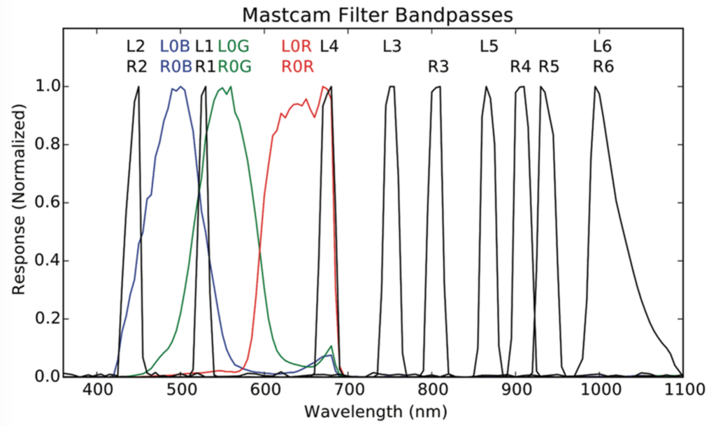
Mastcam filter profiles Measured transmission profiles of the Mastcam Bayer filters (L0 and R0 RGB) and narrowband filters (L1-6 and R1-6). The normalized “response” is the fraction of light at a given wavelength that will pass through the filter material. There are three narrowband stereo filter pairs at 445 nanometers (L2/R2), 527 nanometers (L1/R1) and 1013 nanometers (L6/R6). NASA / JPL / MSSS / Danika Wellington / Jim Bell
Stereo filters have the added benefit of providing redundancy for key wavelength positions, so that if one filter wheel motor fails – or if one camera stops working for any reason – those same colors are available in the other eye. But this redundancy is also a disadvantage, because it limits the total number of colors available between the two eyes.
The team weighed the pros and cons of multiple stereo filters and decided that it would be better to have more colors instead. With only one set of stereo bands – instead of Mastcam’s three – Mastcam-Z could “free up” two filter positions for new wavelengths. These could help fill in some important gaps in Mastcam’s wavelength coverage (more on those later). So the next question was: which filter should be duplicated for stereo?
Ideally, the stereo filters would be in an infrared wavelength where the camera can use the entire spatial resolution of its detector, rather than a visible wavelength where details get interpolated among the checkerboard Bayer pixels. If you require a wavelength where all the filters are equally transparent, it would have to be longer than 840 nanometers. But the longer-wavelength you go, the less ambient light there is on Mars. Considering the various trade-offs, the team selected 800 nanometers for stereo; although this won’t improve the resolution beyond the Bayer filters, it allows for lots of signal-to-noise in a near-infrared wavelength. Plus, this 800-nanometer position is smack-dab in the middle of Mastcam-Z’s range, so it works well as a “join” between the two eyes (we’ll talk more about how the filters are arranged in a bit).
Narrowband Filters for Looking at Rocks
Selecting and positioning the clear, solar, and stereo filters on both cameras left room for 5 more filters in each eye that could be used for possible mineral detection. One early option that the team explored was a set of filters to detect and map sulfate minerals. Sulfates are key remnants of Mars’ more watery past, and various flavors of sulfate minerals were important discoveries at the Spirit, Opportunity, and Curiosity landing sites. Relevant to Mastcam-Z, iron-bearing sulfates have an absorption band near 430 nanometers; it would require three filters at roughly 410, 430, and 445 nanometers to detect the presence and shape of the absorption. At those wavelengths, however, only one in four of the pixels on the camera detector would register any light, because of the Bayer filter pattern. Furthermore, there is very little sunlight at 410 nanometers compared to longer wavelengths; the signal might be very poor. For these reasons, the team decided that the precious filters would be better spent elsewhere.
The Multispectral Working Group assembled a large library of spectra of example minerals that are known or suspected to be present on Mars: sulfates, other water-bearing minerals, and rock-forming minerals and their alteration products. A few years prior, the ExoMars PanCam team went through a similar exercise, and they developed a computer algorithm that determined the optimal set of camera filters to use to tease apart differences among a fixed library of spectra. The Mastcam-Z team contacted the members of the ExoMars PanCam team who had led this effort, Claire Cousins and Matt Gunn, to see if they would be willing to collaborate. They were, and in the summer of 2015 they helped propose an “optimized” filter set for Mastcam-Z.
That filter set had the already-decided stereo filters set at 800 nanometers, and the remaining “optimized” filter positions were pretty evenly spaced out across the full available wavelength range. As it turns out, this suggested wavelength spacing was close to the existing spacing of most of Mastcam’s filters – except for a large gap around 600 nanometers, a wavelength region in which iron-bearing minerals that form by alteration of igneous rocks have spectral features. The team decided, therefore, to preserve all of the original Mastcam wavelength locations, and to add a 605-nanometer filter by using one of the new positions “freed up” from reducing the stereo coverage.
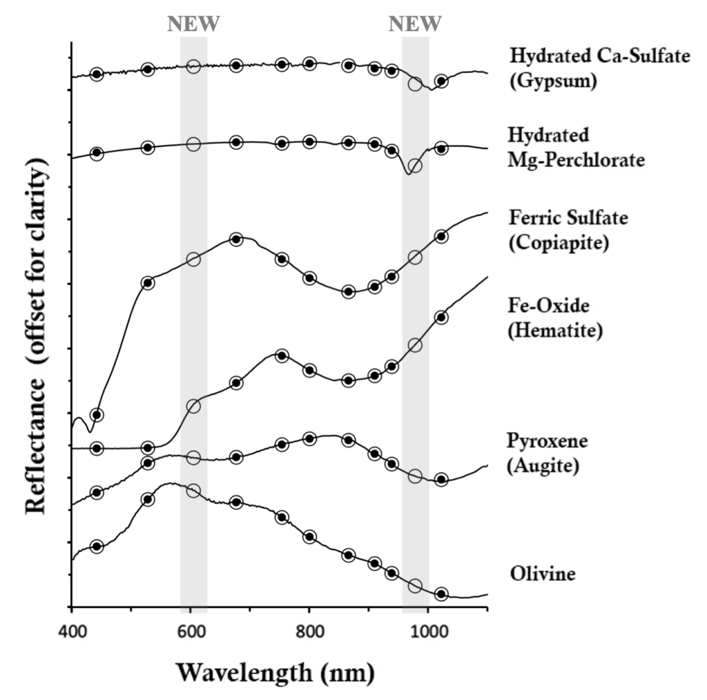
Simulated Mastcam-Z narrowband filter spectra Examples of Mars-relevant mineral spectra (full lab spectra shown as straight lines) that have been convolved to the Mastcam-Z narrowband filter bandpasses (shown as circles). The new Mastcam-Z filter positions at 605 and 978 nanometers highlighted. Melissa Rice / Jim Bell / USGS
The other “freed up” filter position, then, could be used to target a specific part of the near-infrared spectrum important to hydration. Scientists interested in looking for water-related minerals argued for the addition of a filter between Mastcam’s two longest-wavelength filters. In the spectral region between 950 and 1000 nanometers, many hydrated minerals (sulfates, clays, and chlorides, to name a few) have narrow absorptions due to water, with the exact position of the absorption depending on the particular mineral present. For example, the minerals gypsum and magnesium perchlorate have hydration features that aren’t fully captured by Mastcam’s 937 and 1013 nanometer filters. But in the plot above, can you see how the new Mastcam-Z filter – squeezed in at 978 nanometers – helps capture that important absorption?
Arranging the Filters in the Two Cameras
A final major question to answer was: How should the filters be distributed between the two eyes? The Spirit/Opportunity Pancam and Curiosity Mastcam teams had taken different approaches. Pancam put mostly short-wavelength filters in the left eye, and long-wavelength filters in the right eye. Mastcam mixed things up, with some short- and some long-wavelength filters in each eye. The rationale for this choice was that if one of the two cameras failed, there would still be filters spread across the spectrum in the remaining eye – a similar rationale as for Mastcam’s three sets of redundant stereo filters.
But splitting the filters between Curiosity’s two eyes led to unforeseen problems when doing multispectral science, as Mastcam-Z team member Kjartan Kinch explained to the Multispectral Working Group. Seeing the whole spectrum isn’t really what leads to mineralogical identification; rather, you map the possible locations of minerals by comparing images taken in two wavelengths, one inside and one outside a mineral absorption feature. If no mineral absorption feature is present, the pixel values in the two comparison images are similar. If there is an absorption, the pixel value at the wavelength of the absorption will be lower than the pixel value as seen in a wavelength outside the absorption. When the two wavelengths you’re comparing are in different eyes, the data usually turn out to be of lower quality than when they’re taken through the same eye. It’s complicated to say exactly why this is; in part it’s because the two eyes have different points of view (so they see light coming from different angles), and also the two cameras have different amounts of dust coating their lenses, in addition to slight differences within their optics.
The team found Kinch’s arguments compelling and decided to go back to the Pancam way of doing things, putting short-wavelength filters in one eye and long-wavelength filters in the other eye. Incidentally, the ExoMars PanCam team had made the same choice for their filters.
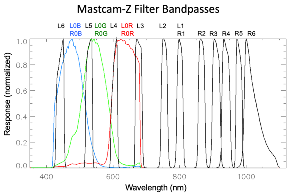
Mastcam-Z filter profiles Measured transmission profiles of the Mastcam-Z Bayer filters (L0 and R0 RGB) and narrowband filters (L1-6 and R1-6). The normalized “response” is the fraction of light at a given wavelength that will pass through the filter material. The narrowband filters L1 and R1 are the same at 800 nanometers for stereo. NASA / JPL / MSSS / Melissa Rice / Alex Hayes / Jim Bell
Spectra from Mastcam-Z’s two eyes can be tied together with the RGB imaging from the “clear” L0 and R0 filters. They’ll also be tied together at the 800-nanometer stereo wavelength. It makes sense, then, to have this 800-nanometer wavelength serve as a single tie point between the two eyes; all the non-RGB filters at wavelengths less than 800 nanometers will be in the left eye, and all the non-RGB filters greater than 800 nanometers will be in the right eye. Locating the short-wavelength filters in the left eye is also good for cross-calibration with SuperCam, the upgraded version of Curiosity ChemCam for Perseverance. SuperCam’s single eye is located above the left eye of Mastcam-Z, and it gathers spectra in the shorter wavelengths, from about 400 to 840 nanometers.
Speaking of SuperCam, the team also decided to “fatten up” the L5 filter in order to see SuperCam’s green laser, which is at 532 nanometers. The L5 band is centered at 528 nanometers, but with a larger bandwidth than Mastcam’s equivalent filter, so it should allow light from the laser pass through. Now, if Mastcam-Z takes an image with L5 at the same time that SuperCam “zaps” a rock, the image should capture the bright light – like a laser pointer on Mars! This isn’t scientifically necessary, but it’s very cool.
Another way in which the Mastcam-Z filter wheels will harken back to the way that the Spirit and Opportunity Pancams worked is that the filter wavelengths will be organized in wavelength order on their filter wheels. As Mastcam-Z cycles step by step through the right filter wheel, it will cycle step by step up the spectrum, from R1 (800 nanometers) to R6 (1022 nanometers). For the left filter wheel, the cycle will start at L1 (800 nanometers) and cycle down the spectrum to L6 (442 nanometers). Apart from the scientific reasons, Kinch argued that this organization would help the Perseverance team easily memorize the filter set, which he said is important “if we want the wider science team to utilize Mastcam‐Z as much as possible and experience as little friction as possible in doing so.”
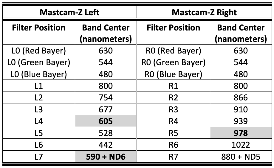
Table of Mastcam-Z filter wavelengths The shaded wavelengths are the ones that have been added to the heritage MSL/Mastcam filter set. L7 and R7 are the solar filters with neutral density filters.
So that means that the Mastcam-Z left eye will get five filters that are up to 800 nanometers, and the right eye will get five filters longer than 800 nanometers. The images below, of the actual filter wheels before the filters themselves were installed, show the final arrangements of the various filters:
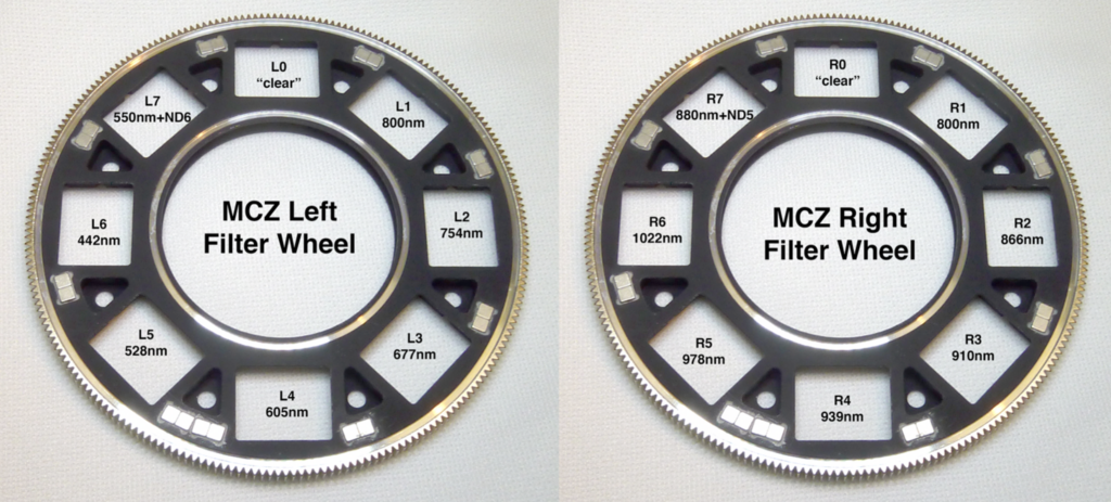
Mastcam-Z filter wheels Photo of the left and right filter wheels before the filters themselves were added, annotated with the filter names and wavelengths. NASA / JPL / MSSS / Mike Caplinger/ Melissa Rice. For scale, each wheel is approximately 80 mm (3.1 inches) in diameter.
One final difference you’ll notice – if you compare these images to Mastcam’s filter wheels depicted in the earlier figure – is that Mastcam-Z’s holes for the filter materials are rectangular instead of circular. That’s to make sure the light passing through the filters hits all parts of the detector. (In full-size Mastcam images, there’s a subtle darkening in the corners due to the circular shape of the filter wheels. This is an effect called “vignetting,” which gives photos on Instagram a cool, olde-timey look, but which isn’t ideal for scientists who want to scrutinize every pixel!)
Testing out the Filters on Earth Rocks
All of these decisions were made by early 2016, when assembly of the Mastcam-Z hardware began at Malin Space Science Systems (MSSS) in San Diego. (The same shop also led the design and fabrication/testing of the Curiosity Mastcams.) At that point the team delivered the requested filter specs to Materion, the company that created the filter materials for Pancam, Mastcam, and now Mastcam-Z.
By early 2019, MSSS had glued the filters into the filter wheels, and assembled the wheels with the optics, motors, detector, housings, electronics, and wiring to buld the cameras. The Mastcam-Z team had a short window of time to test out Mastcam-Z’s full color capabilities under controlled conditions before delivering the flight hardware to the Jet Propulsion Laboratory to be integrated with the rover.
As part of these calibration activities, the Multispectral Working Group designed a Geology Board (or “Geoboard”) for Mastcam-Z to photograph with its full filter set. The Geoboard had flight spares of the calibration targets and a variety of natural Earth rock samples that are similar to rocks we expect – or hope – to find on Mars. These included sulfate evaporite deposits from ancient dried-up seas, carbonate-coated breccias from a volcanic vent, stromatolites built by ocean algae mats, and basalt volcanic rocks that have been exposed to wind and weather, to name a few.
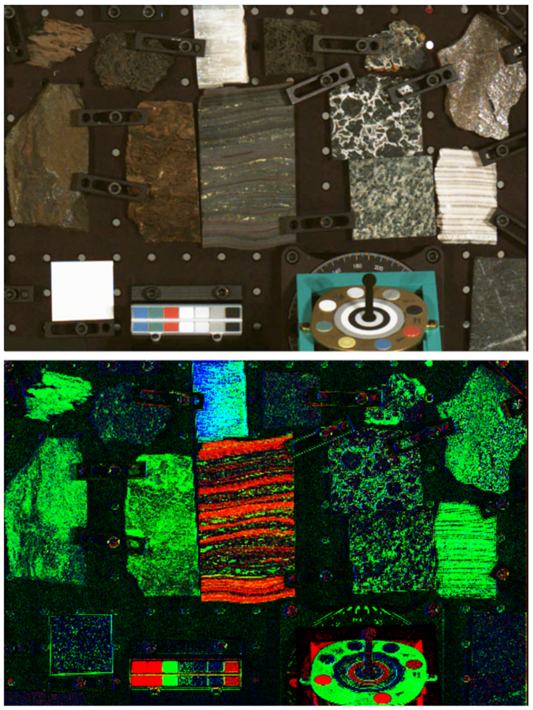
Mastcam-Z images of rocks and calibration targets Images taken at Malin Space Science Systems during Mastcam-Z calibration. Above: RGB image from the R0 filter. Below: color composite image made with the narrowband images. Red is the band depth at 866 nanometers, green is slope between 637 and 1022 nanometers, and blue is the slope between 978 and 939 nanometers. For scale, the grid of holes on the board has 1 inch spacing. NASA / JPL / MSSS / Mike Caplinger/ Melissa Rice
Take a good look at the two images above. The top one is a simple RGB image from the R0, or right-eye clear filter. This is a close approximation to how your own eye sees color, and it’s the kind of color imaging that Mastcam-Z will do most of the time on Mars. The bottom image is made from Mastcam-Z’s narrowband filters, which have been processed in a special way that highlights different aspects of the mineralogy. Red here indicates where the R2 866-nanometer filter image is darker than its neighboring-filter images), caused by an absorption due to the presence of iron oxide in the mineral hematite. The red stripes in the center rock are showing that the rock contains alternating bands of iron oxide – and this rock is indeed a sample of a Banded Iron Formation. You can see how it’s a lot easier to see those alternating bands of iron-oxide rich and (relatively) iron-oxide poor rock in the bottom image than in the RGB image above it.
Blue in the bottom image shows where there is an absorption feature at 978 nanometers, where the R5 filter image is darker than the R4 filter image. This was the filter that the team specifically added to see the presence of water in some minerals. It’s capturing the hydration in a sample of gypsum in the top center of the image. To the human eye, that gypsum rock looks very similar to the other white materials on the Geoboard. To Mastcam-Z, however, it is obvious which rock has water locked in its mineral structure. Isn’t that cool?
The conditions in the clean room couldn’t replicate the exact conditions that Mastcam-Z will be encountering on Mars. For one thing, the lighting was different, and the clean room certainly had no dust. Most importantly, the rocks on the Geoboard were clean, ideal standards, selected to make the mineralogic differences as obvious as possible. In Jezero crater on Mars, even if the same minerals are present, the differences probably won’t “pop” out this clearly in our images. However, these calibration images are still an excellent sneak preview of Mastcam-Z’s color capabilities – and of how Perseverance will see Mars more like a real Martian would.
The poet William Butler Yeats wrote that “The world is full of magical things – patiently waiting for our senses to grow sharper.” Mars is now part of our world as well, full of wondrous things that Perseverance will start exploring on February 18, 2021, with senses sharper than ever before.
Make sure to check the Mastcam-Z website to see the images fresh from Mars. Carrying on the tradition set by Spirit and Opportunity, all the images from Perseverance will be shared with the public within hours of arrival on Earth.
And for more details on the science goals and technical specifications on the Mastcam-Z instruments, check out the following Open Access instrument paper: https://link.springer.com/article/10.1007/s11214-020-00755-x